Regimes
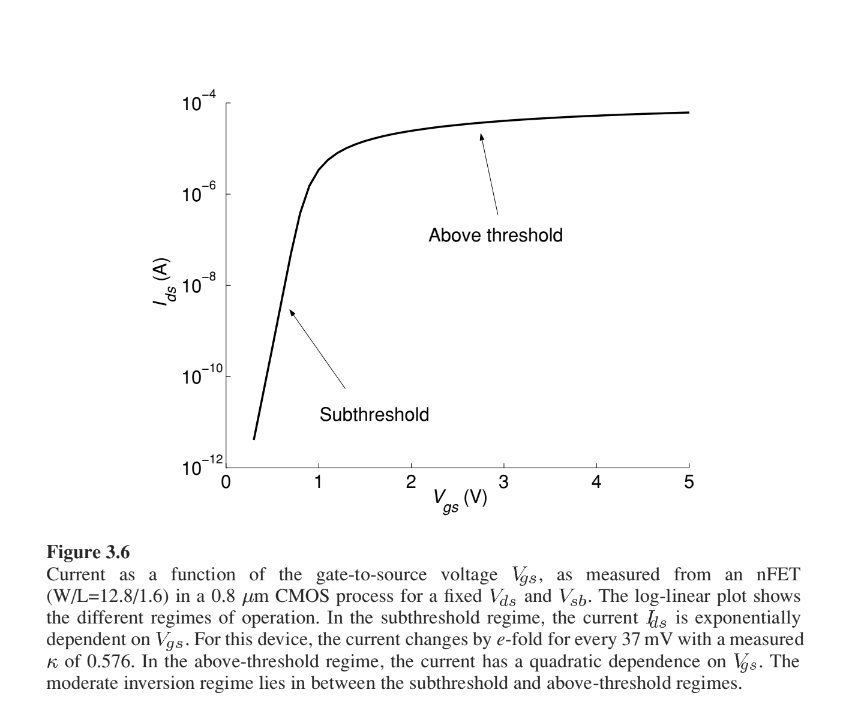
We first consider current as a function of gate to sourcwe voltage $V_{gs}$.
Subthreshold Regime
Small voltage are reduced so low power consumption. Current flows primarily by diffusion.
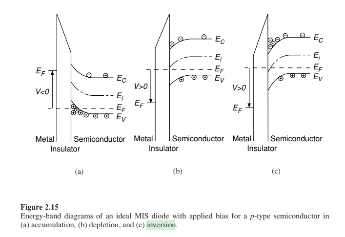
Increasing the gate voltage increases the positive charge on the gate. This charge repels the holes in the substrate and leaves behind negative ions that balance out the gate charge. The MOSFET operates in the sub-threshold regime when the positive charge on the gate is almost balanced by the negatively-charged depletion region underneath the gate. There is also a very thin layer of electrons beneath the gate (the inversion
layer) but it is negligible in this regime.
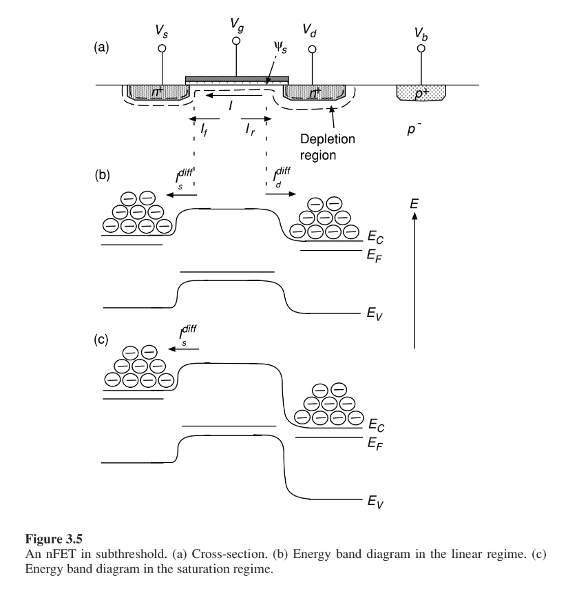
In these diagrams, the axis for the electron energy is directed upwards, while the positive voltage axis is downwards. That is, the quasi-Fermi level of the region that has a higher applied voltage (like the drain of the transistor) is lower than the quasi-Fermi level of the source region. Because the barrier at the drain is higher than that at the source, the electron concentration at the drain end of the channel is lower than at the source end. The concentration gradient leads to the diffusion of electrons from the source to the drain. The electrons that diffuse to the drain end of the channel are swept into the drain by the electric field in the depletion region around the drain. The electrons in the channel form an inversion layer. As the gate voltage increases, the depletion region also increases so that the negative charge in this region balances the increased positive charge on the gate. The surface potential relative to the bulk also increases because of the wider deple-
tion region.
Doing the math for carrier densities and surface potential leads to the following equation:
$I =I_{0}e^{\kappa V_{g}/U_{T}}(e^{-V_{s}/U_{T}}-e^{-V_{d}/U_{T}})$
that can be separated into $I_{f}$ and $I_{r}$:
$I=I_{f}-I_{r}$
where:
- $I_{f}=I_{0}e^{(\kappa V_{g}-V_{s})/U_{T}}$
- $I_{r}=I_{0}e^{(\kappa V_{g}-V_{d})/U_{T}}$
The forward component depends only on $Vgs$, while the reverse depends only on $Vgd$.
Regions of operation
We have different regions of operation depending on $Vds$.
Triode/linear
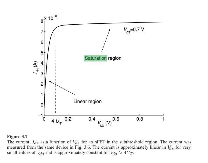 The current depends on $Vds$. This region describes the operation of the transistor for small $Vds$.($\leq 4U_{T}$)
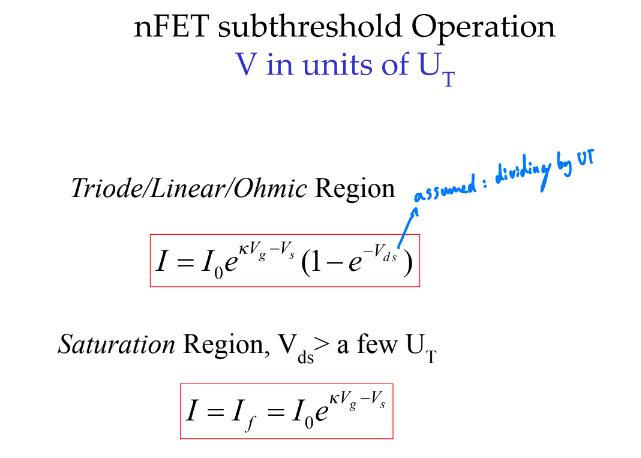
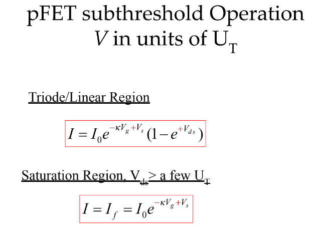
- $I = I_{0}e^{(\kappa V_{g}-V_{s})/U_{T}}(1-e^{-V_{ds}/U_{T}})$
Taking Taylor's expansion series, we can show that $I$ is approximately linear with $V_{ds}$ for $V_{ds}\leq U_{T}$.
note on kappa:
- $\kappa$ is the capacitive coupling ratio:
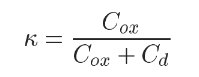
- It is also the slope of the log linear plot of $I$ vs $Vg$ in subthreshold (subthreshold slope factor).
- It varies slowly with $V_{g}$ but is assumed as constant
- Ranges from $0.5$ to $0.9$
Saturation
The current is independant of $Vds$.
As $Vds$ increases beyond $4U_{T}=100mV$, the concentration of electrons at the drain can be neglected compared to the source because of the large barrier height.
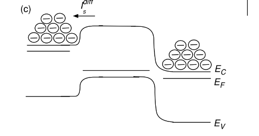
Any electrons in the channel that diffuse close to the drain are immediately swept into the drain by the electric field. The diffusion current no longer depends on the electron concentration at the drain, the current in the transistor only depends on $V_{s}$ and is equal to $I_{f}$. The relationship is described by:
$I=I_{f}=I_{0}e^{(\kappa V_{g}-V_{s})/U_{T}}$
The current is approximately constant.
Summary
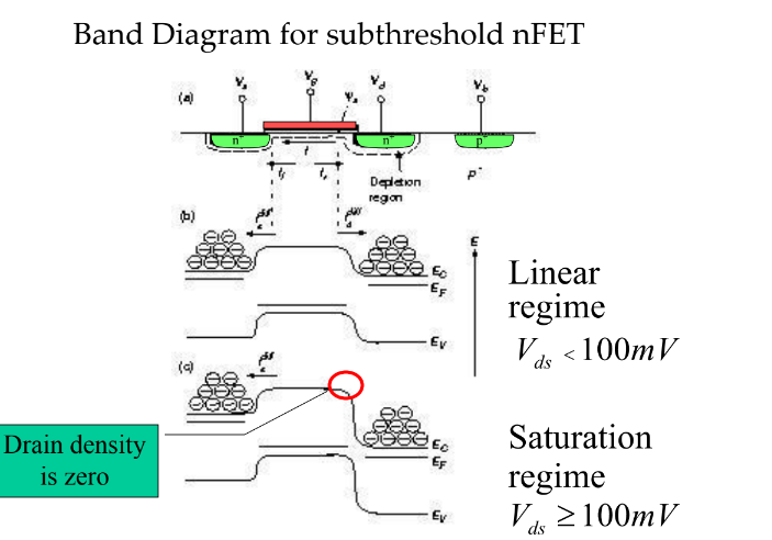
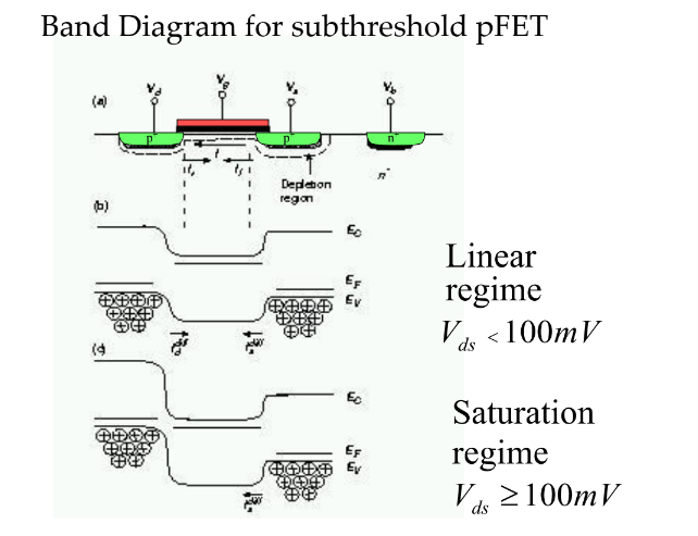
Above threshold regime (or strong inversion)
To understand this regime, we need to understand how mobile charge density depends on $V_{gs}$.
Inversion occurs when the intrinsic Fermi level crosses the Fermi level near the surface, corresponding to the situation where the minority carrier density is larger than the majority carrier density at the surface.
Capacitive divider circuit
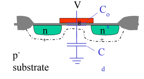
The depletion layer doews not contain any mobile charge and can be regarded as a capacitor.
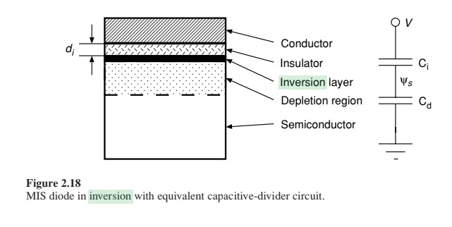
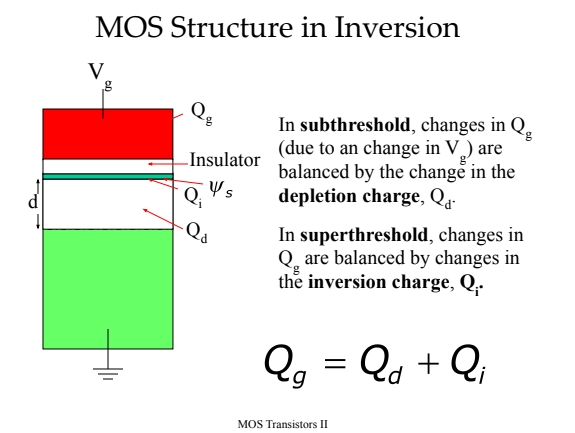
The superthreshold region is delimited by $Vth$ that is the voltage at which the extrapolated $Ids$ is equal to $2Ids$ (it depends on $Vg$). We can view the overdrive voltage as $Vg-Vt$.
Overdrive voltage
Why such an abrupt threshold ?
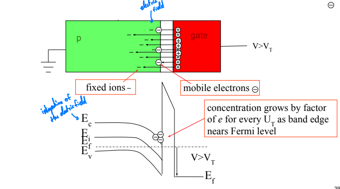
meaning of $\kappa$:
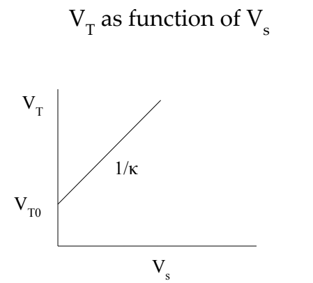
$\frac{1}{\kappa}$ is the efficiency of the source in raising the threshold voltage.