Neuromorphic Circuits
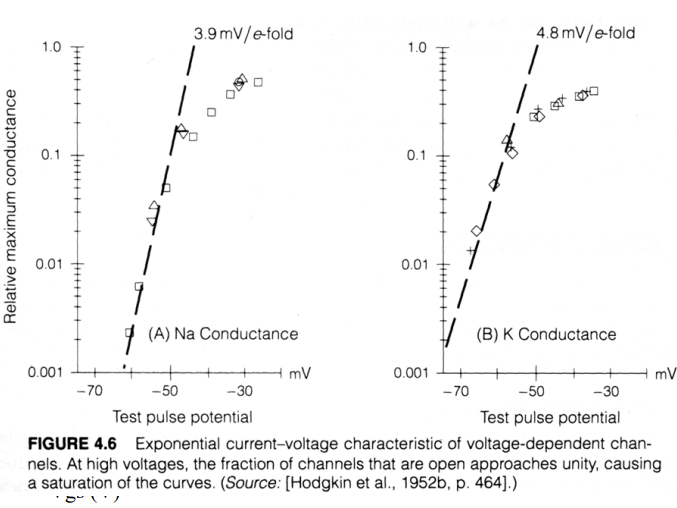
Neuromporphic circuits make use of analog subthreshold electronic circuits. The perfect emulation of the biophysics of proteic channels.
Why transistors?
By varying the gate voltage we are able to control the amount of current flowing through the transistor (in an exponential manner).
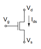
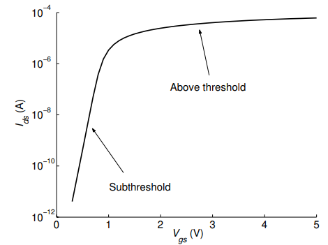
The transistor can operate in two regimes. Subthreshold and above threshold.
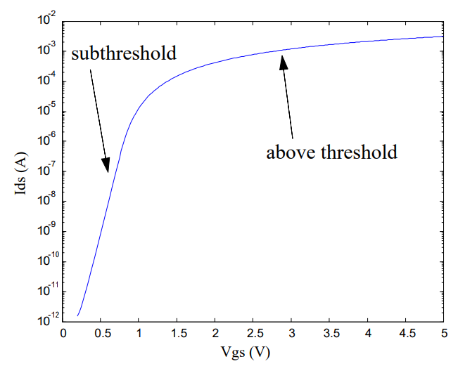
Here we can see that the curve is similar to an IV curve from a channel.
N-FETs
Subthreshold
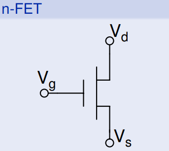
Where the bulk, $V_{b}$ is connected to $GND$. The current flows from drain to source (think about electron source) and depends on:
$I_{ds} = I_{0}e^{\kappa V_{g}/U_{T}}(e^{-V_{s}/U_{T}}-e^{-V_{d}/U_{T}})$
which is equivalent to:
$I_{ds} = I_{0}e^{\kappa V_{g}/U_{T}-V_{s}/U_{T}}-I_{0}e^{\kappa V_{d}/U_{T}-V_{s}/U_{T}}= I_{f}-I_{r}$
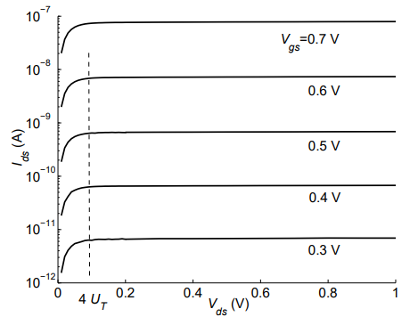
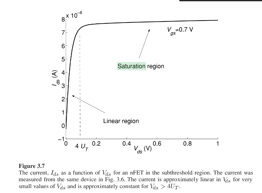
If $V_{ds} > 4 U_{T}$ the $I_{R}$ term becomes negligible and we operate in the saturation regime and the equation simplifies to
$I_{ds} = I_{0}e^{\kappa V_{g}/U_{T}-V_{s}/U_{T}}$
Variables
- $I_{0}$ current-scaling parameter.
- κ subthreshold slope factor $\kappa = \frac{C_{OX}}{C_{OX}+C_{dep}}$.
- $U_{T}$ the thermal voltage.
- $Vg$ the gate voltage,
- $Vs$ the source voltage,
- $Vd$ the drain voltage
In subthreshold, for a constant $I$, a $ΔV$ change in the source voltage means that the gate voltage has to increase by $𝜅ΔV$ and not just $ΔV$.
Current characterisation
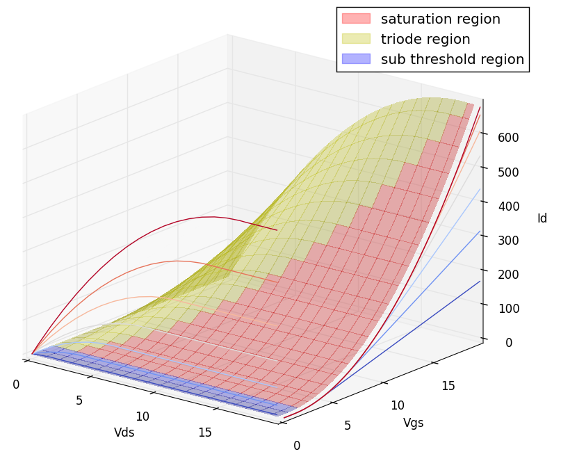
Given a ready made transistor, we can influence $I$ with $V_{gs}$ and $V_{ds}$
We can view this in three dimensions to get a better grasp of it.
P-FETs
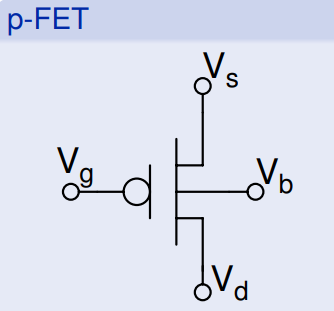
Where the bulk, $V_{b}$ is connected to $V_{dd}$

Operating regimes

Subthreshold
Linear or ohmic or triode
Saturation
$V_{ds}>4U_{T}(100mV)$
As increases beyond , the concentration of electrons at the drain end
of the channel can be neglected with respect to the concentration at the source
end because of the larger barrier height as shown in Fig. 3.5(c). Any electrons
in the channel that diffuse close to the drain are immediately swept into the
drain by the electric field in this region. Because the diffusion current is no
longer dependent on the electron concentration at the drain, the current in
the transistor depends only on and is approximately equal to.
This region of operation is called the saturation region. As seen in Fig. 3.7, the
current is approximately constant in this region. Figure 3.8 shows a family
of curves measured from the same nFET in the subthreshold region with gate
voltages ranging from $0.3 V$ to $0.7 V$.
In these curves, the transition point fromthe linear region to the saturation region occurs around $V_{ds}=100 mV$ and is independent of the gate voltage.
Superthreshold

The equations change a bit, but luckily we dont work much in this regime
Saturation
Triode
The circuits
- Diode connected FET
- Current source
- Current mirror
- Differenial pair
- Current correlator
- Source follower
- Bump anti bump
- Unity gain follower
- Transampedance amplifier
- Follower integrator and differentiator
- WTA
- Photoreceptor
- Neurons
- Transconductance amplifier
- Spike generating mechanism
- Conductance based neuron
- Generalized integrate and fire
- Integrate and fire neuron
- Current mode DPI
- Synapse analog circuit