Differenial pair
Summary
Input: $\Delta V =V_{1}-V_{2}$
Output: $I1$ and $I_{2}$ (if saturation)
Settings: $V_{b}$ for $I_{b}$
Notes: For it to work $M_{b}$ must be in Regimes > Saturation
This circuit is similar to the source followe, only the biais current is shared between $M_{1}$ and $M_{2}$. If all MOSFETs are operated below threshold and in saturation and we assume that and have the same subthreshold slope factor $\kappa$.
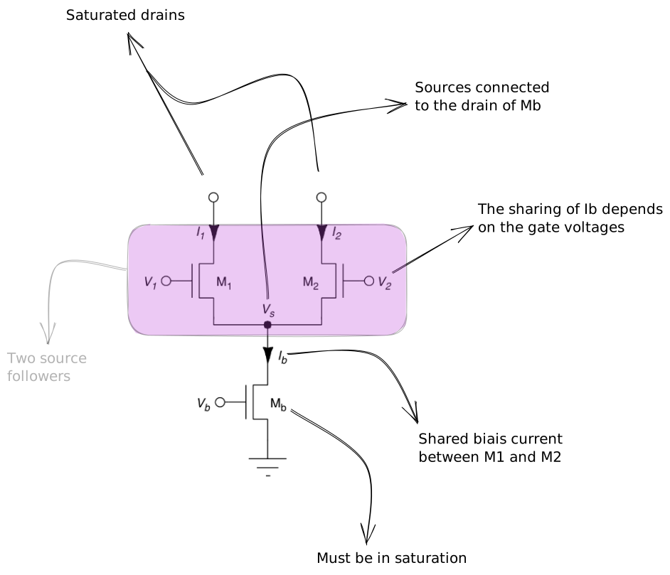
%%🖋 Edit in Excalidraw, and the dark exported image%%
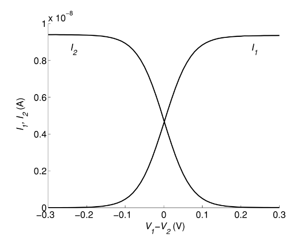
The dependance of $I_{1}$ and $I_{2}$ can be seen in the next graph, where the curves have a sigmoidal shape. For small $\Delta V$ the behaviour is linear, and for large $\Delta V$ there is plateau at $I_{b}$.
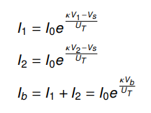
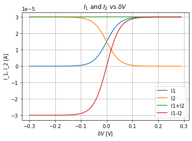
written in canonical sigmoid form:

Mb saturation
$M_{b}$ is in saturation if:
$e^{-V_{s}/U_{T}}\ll 1$
and if $\mid V_{1}-V_{2}\mid > 4U_{T}$ it becomes:
$max(V_{1},V_{2})>\kappa^{-1}(4U_{T}+\kappa V_{b})$
If $M_{b}$ is not in saturation the output will depend strongly on the common mode of the inputs
Uses
Compressive non-linearities are very useful for implementation of different functions (ex: neural networks). The output currents depend only on the difference of the input voltages: The circuit has a small common-mode sensitivity. Given that voltages are differential-mode rather than absolute quantities such a property is very useful.
This circuit is also combined with the Current mirror (to implement an $I_{1}-I_{2}$ output ) to get the Transconductance amplifier.
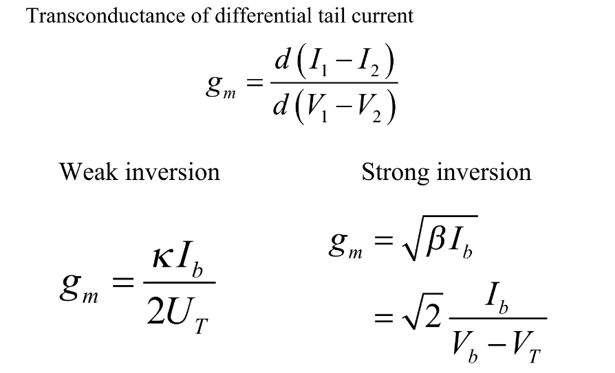
Transconductance